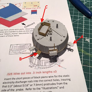
On to the model. Opening the box you have a few pages of what look like instructions, a well detailed base. The major parts of the probe are very well detailed. Then I see that there's a gouge on the edge of the dome portion of the lander. Dang. But it can be filled. The myriad of TINY parts for the probe are extremely well detailed. A large fret of Photo etch also looks well done -
There's a CD to download the instruction sheet in a pdf. Excellent I thought. My biggest complaint to the Garage Kit guys, is that in some circumstances, they have images on their instructions that look like the 20th generation copy of a copy and you can barely make anything out.
I download the pdf, and then print it out 30+ pages! The images? The same blurry pics that I've grown to dislike ...
Starting with the major components, I ran into my first snag with the central ring (I don't have the instructions with me so I know I'm not calling the parts by their correct name). There is a "shelf" on one side. It's very symmetrical and looks like it belongs there as opposed to a piece of flash. Looking at the instructions, there's no indication whether it belongs there or not. I leave it for now.
In between the parts are PE rings that need to be installed-
But when installing the 3 major parts, the instructions say something to the fact that the parts need to be lined up exactly. Oh boy! The instruction images aren't clear enough to show positioning, and there's nothing, say on the inside of the part to indicate the correct lineup. Luckily further back in the instructions there's an image where I can make out what goes where. So the main bus gets together. That "shelf" is supposed to be cut off.
As evidenced by the faint grow marks on some of the larger parts, this kit was made by 3D drawing. IMHO there are many parts that were made for the rivet counter, being built as the real guys would build the real thing. For instance there's a PE disc (C) that sits on prolly a 1/2mm protrusion. Is this really necessary or could a disc shape be drawn onto the top of the lander?
Another example is (B) where one piece of PE has to be folded and then centrally glued to a second piece of PE. Could this just be one piece?
IMHO the answer to both is yes.
As I said the 3D model looks like it was put together as the technicians put the real one together. Meaning many of the separate parts are TINY and you only get one.
It gets frustrating if these tiny parts easily go flying. If the carpet monster does it's job you're SOL except to email Space Cadet and ask for more.
The below picture are 3 parts glued together. This doesn't even include that I left out two 32guage pieces of wire that connect each side of the "T" section. Those cross pieces went flying numerous times. Thankfully I was able to find them. As you can see the whole sub-assembly is less than 1 cm long.
After looking for where part (B) above goes - there's two very faint lines and gluing 2 of the 4 assemblies I was done.
Part 2 upcoming. Thanks for looking.


No comments:
Post a Comment